Testing Guidelines
Resistance Is NOT Futile
Resistance is the limitation of current through a wire. Knowing the correct resistance of a wire will result in more accurate testing.
Do you know the correct resistance settings when building a new test program? While the default settings may work in most situations, you may find tests failing because of a wrong setting—not because of a bad cable. One of the most common settings in a situation like this is the resistance setting.
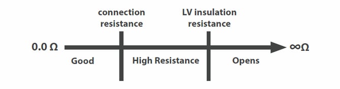
The resistance values are found in the low voltage settings of the test program. One setting is for connection or wire resistance while another sets insulation resistance. The tester will use these values to determine if the cable is good.
All this is explained in the diagram below.
If your cables are constantly failing tests due to resistance errors, you may want to adjust the resistance settings. Cirris has tools and articles that explain how to do this.

Further Reading:
Resistance is the limitation of current through a wire. Knowing the correct resistance of a wire will result in more accurate testing.
Four-wire Kelvin testing provides a more accurate resistance measurement.
Using 4-wire Kelvin testing to measure resistance down to 1/10,000th of an ohm, Cirris carefully cut strands of a wire and recorded the results.