Guidelines for Setting Resistance Test Thresholds
Among other things, cable testers are used to ensure that cable assemblies do not have OPENS or SHORTS. In simple terms it looks like this:
Intended connections:points that ARE intended to be connected by wires. |
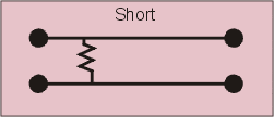
Not-intended connections:points, or wires, that are NOT intended to be connected, are called (SHORTS). |
|

|

|
Cable testers measure the resistance between all test points to determine if there are, or are not, connections.
The big question is: at what resistance threshold are OPENS and SHORTS detected?
Basic Go/No Go Continuity Tester
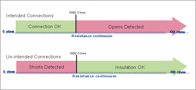
Basic continuity testers generally have one fixed threshold (the resistance is usually not very accurate and can range from 100 to 10,000 ohms). Resistances measured under this threshold are seen, while resistances measured above this threshold are not seen. Whether they are OPENS or SHORTS is determined by whether they are intended connections or not, as illustrated by this graphic.

Cable Testers with Selectable Resistance Thresholds
Cable testers that have variable resistance thresholds allow you to set the measured resistance value that will determine pass/fail test status as illustrated by this drawing.

To set an appropriate Connection Resistance Threshold you must first determine the nominal resistance of the wires you are testing. For help determining standard wire resistance click here.
Recommended Connection Resistance Test Settings*
| Stringent Test | Good Test | Moderate Test |
| 1.05 of Actual Resistance + .5 ohms |
Greater of either 2 ohms or 1.10 of Actual Resistance + 1 ohm |
Greater of either 5 ohms or 1.20 of Actual Resistance + 2 ohms |
*Note: for very low resistance measurements use 4-wire Kelvin Testing. For more information on 4-wire Kelvin Testing click here.
Recommended Low Voltage Insulation Resistance Test Settings*
| Stringent Test | Good Test | Moderate Test |
| 5 Meg Ohms | 500K ohms | 100K ohms |
*Note: while a Low Voltage Insulation Resistance test does a better job of finding shorts, it is NOT as effective as HV insulation resistance testing. Click herefor more information on HV insulation testing. A low voltage specification for Insulation Resistance is not important when HV tests are performed.
Using Dual-Resistance Settings to Ignore Embedded Components
Cirris testers use dual-resistance thresholds. The lower threshold (components >) is used to verify that wires/points connected via diodes, resistors, and/or capacitors are tested for shorts. The higher threshold (IR) is used to verify that wires/points not connected to such components are tested at a more stringent LV Insulation Resistance value to all other such wires/points. For more info on testing components go here.

Table of Cirris Testers with Adjustable Resistance Thresholds
| Model | Connection Resis. Range |
4-Wire Connection Resistance Range |
Low Voltage Insulation Resistance MAX |
High Voltage Insulation Resistance Range |
Components Tested |
| 1000RX | .1 – 10KΩ +50KΩ, 100KΩ, 500KΩ, 1MΩ, 5MΩ |
N/A | 5M Ω | N/A | Resistors Diodes |
| 1100R+ | .1 – 100KΩ 500KΩ, 1MΩ, 5MΩ |
.005 – 10Ω | 5MΩ | N/A | Resistors Diodes Capacitors |
| 1000HX | .1 – 100KΩ 500KΩ, 1MΩ, 5MΩ |
.001 – 10Ω | N/A | 5MΩ – 500MΩ | Resistors Diodes Capacitors Twisted Pairs |
| 1100H+ | .1 – 100KΩ 500KΩ, 1MΩ, 5MΩ |
.001 – 10Ω | 5MΩ | 5MΩ – 1GΩ | Resistors Diodes Capacitors Twisted Pairs |
| Touch 1 | .1 – 100KΩ | .001 – 10Ω | 5MΩ | 5MΩ – 1GΩ | Resistors Diodes Capacitors Twisted Pairs LED’s Zener Diodes |
| Easy-Wire® CR | .1 – 1.0M Ω | .005 – 75Ω | 100&Omega – 500KΩ | N/A | Resistors Diodes Capacitors |
| CH+ | .1 – 100KΩ | .001 – 10Ω | N/A | 5MΩ – 1GΩ | Resistors Diodes Capacitors Twisted Pairs |
| CH2 | .1 – 1M Ω | .001 – 100Ω | N/A | 5MΩ – 1GΩ | Resistors Diodes Capacitors Twisted Pairs |
| Easy-Touch® | .1 – 100KΩ | .001 – 10Ω 2nd Qtr. 2011 |
5MΩ | 5MΩ – 1GΩ | Resistors Diodes Capacitors Twisted Pairs LED’s Zener Diodes |

